Tuesday 18 September 2012


Axial Flow Pumps And Fans

The figures below are for an Axial Flow Propeller fan pumping air.
22109/img_axf1.png
+
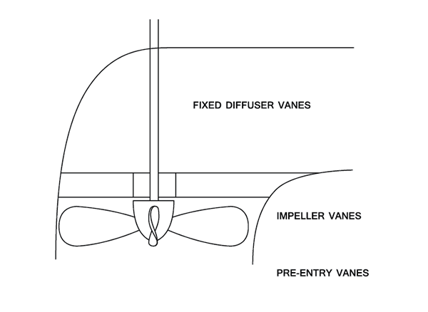
Leonhard Euler (15 April 1707 - 18 September 1783) was a pioneering Swiss mathematician and physicist. He made important discoveries in fields as diverse as infinitesimal calculus and graph theory.
22109/img_axf2.png
+
Notes:
  • The fixed diffuser vanes are used to remove the whirl component of the discharge velocity of the impeller and to convert the energy to Pressure.
  • The impeller vanes may be adjustable.
  • The machine may be fitted with pre-entry vanes to ensure that there is no pre-rotation and that the flow is purely Axial.
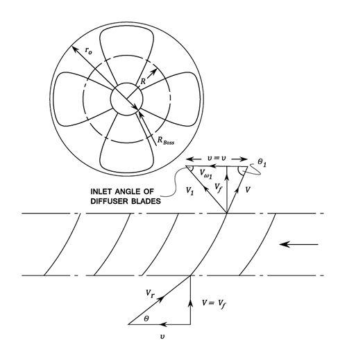
  • The bottom diagram is produced by considering a Radius R of the impeller and drawing it out in a flat plane.
v_1 = v = \frac{2\pi RN}{60}
The flow through the machine q = \pi \left(r_0^2 - r_{boss}^2 \right)\times V_f (The boss area can be neglected).
Also, V = V_f = V_f1 (Blade area neglected).

Euler Theory

Work done by the Vanes per lb. of water = \displaystyle\frac{V_{w1}v_1 - V_wv}{g} = \displaystyle\frac{V_{w1}v}{g}\;ft. (V_w = 0)
Hydraulic or Manometric \eta  = H_m\div \displaystyle\frac{V_{w1}v}{g}
Where H_m = The Manometric head minus the Head developed by the Pump across the Flanges.
Applying Bernoulli's equation across the Vanes:
\frac{p}{w} + \frac{V^2}{2g}\;+\frac{V_{w1}v}{g} = \frac{p_1}{w} + \frac{v_1^2}{2g}
(Neglecting losses in the Vanes)
Therefore the Pressure rise across the Vanes is given by:
\frac{p_1 - p}{w} = \frac{V_{w1}v}{g} - \frac{V_1^2 - V^2}{2g}
But, V_1^2 = V_{w1}^2 + V_{f1}^2 = V_{w1}^2 + V_{f}^2 = V_{w1}^2 + V^2
\therefore\;\;\;\;\;\frac{p_1 - p}{w} = \frac{V_{w1}v}{g} - \frac{V_{w1}^2}{2g}

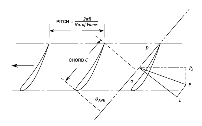
Aerofoil Theory Applied To Propeller Pumps

The Combined Inlet and Outlet and Inlet Triangles.
22109/img_axf3.png
+
The Blades are considered to be aerofoils in cascade in a fluid stream of Velocity V_r Average in a direction \theta to the tangent.
22109/img_axf4.png
+
Force P exerted by the Fluid on the Vane element i is the vector Sum of the lift L and the force exerted on the Vane by the Fluid. The components of P are P_t in the Tangential Direction and P_a in the Axial Direction.
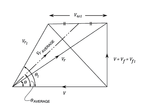
Torque, also called moment or moment of force, is the tendency of a force to rotate an object about an axis, fulcrum, or pivot. Just as a force is a push or a pull, a torque can be thought of as a twist.
Consider an elemental Vane thickness dR at Radius R.
From Aerofoil Theory Lift, L = C_L\;\times \;\displaystyle\frac{1}{2}\rho V_{r\;ave.}^2\;\times C\;dr\;\;lb.
And Drag, D = C_D\;\times \frac{1}{2}\rho V_{r\;ave.}^2\;\times C\;{dR}\;\;lb.
C_L and C_D are lift and drag coefficients depending upon the aerofoil section and the angle of incidence.
Resolving L and D in the direction of motion.
P_t = L\;sin\,\theta _{ave.} + D\;Cos\,\theta _{ave.}\;\;\;\;lb./Vane
P_a = L\;Cos\,\theta _{ave.} - D\;Sin\,\theta _{ave.}\;\;\;\;lb./Vane
D is commonly small compared with L and the second terms are often neglected.
For N Vanes the Total Tangential Force = n\;P_t
= n\left(L \sin \theta _{ave.} + D \cos \theta _{ave.} \right)
Therefore, Torque = nP_t\times R
The Horse-Power required to rotate the Vane elements = \displaystyle\frac{2\pi NT}{33000}
The Efficiency \eta = W.H.P. out put / H.P. in put
Where W = Weight of flow through the annular ring = w\times 2\,\pi\;RdR \times V_f
The Total Axial Force = n Pa If \Delta p is the pressure drop across the vanes, \Delta p\times 2\pi \,R\,dr = nP_a
This equation can be solved to find \Delta p.
[imperial]
Example - Example 1
Problem
For the Axial Flow Propeller it is required to find the torque /ft. radius using both Aerofoil and Euler Theories.
We know the radius R is 3.2 ft and the speed N is 450 r.p.m.
Workings
V = V_f = V_{f1} = 131\;ft./sec and \rho  = 0.074\;lb/ft^3
Theoretical Head = 114 ft. of air.
\eta _H = 0.9\;\;\;\;\;\;\;\;\;\;\;\;\;\;n = 12 Vanes

C_L = 0.44\;\;\;\;\;\;\;\;\;\;\;\;\;\;\;C_d = 0
Chord = 1.1 ft.
It is required to find the Torque per ft radius
\eta _H = H_M\div \frac{V_{w1}V_1}{g} = 114\div \frac{V_{w1}v_1}{g}
But, v_1 = v = \displaystyle\frac{2\pi RN}{60} = 151\;ft./sec.
\therefore\;\;\;\;\;V_{w1} = \frac{114\times 32.2}{0.9\times 151} = 27\;ft./sec.
Velocity triangle:
V_{r\, ave.} = 131^2 + (151 - 13.5)^2 = 190\;ft./sec.
\theta _{ave.} = Tan^{-1}\frac{131}{151 - 13.5} = 43^0\;36'
Lift = C_L\times \displaystyle\frac{1}{2}\rho V_{r\,ave.}\times C\times dR
= 0.44\times \frac{0.074}{2\times 32.2}\times 190^2\times 1.1\;lb./ft.radius
= 20.1 lb./ft. radius
P_t = 20.1\times Sin\theta _{ave.} = 13.85\;lb./ft. radius
For twelve Vanes the longitudinal Force = 12 Pt
Therefore, Torque required = 12\;P_t\;R = 12\times 13.85\times 3.2 = 532\lb.ft./ft.\radius
Note:
Axial thrust / blade P_a = L\,cos\,\theta _{ave.}
= 20.1\times Cos\,45^0\;36' = 14.55\;lb./ft.\;width
Total axial Force for 12 Vanes = 14.55 X 12 = 174.6 lb./ft. width
If \delta\,p is the pressure rise, then \Delta p\times 2\pi \times  R\,dR = 174.6 lb./ft.
\therefore\;\;\;\;\;\Delta p = \frac{174.6}{2\pi \times 3.2} = 8.68\;lb./ft^2
Or, \;\;\;\;\Delta p = \displaystyle\frac{8.68}{0.074} = 117.3\;ft.\;of\;air

An Alternative Approach Is:

The weight of Flow through an annular element, W = 2\pi \;R\,dR\times V_f\times w
= 2\times 3.2\times \pi \times 1\times 131\times 0.074 = 195\;lb./sec.
Work done per lb per lb.
= \frac{V_{w1} v_1}{g} = \frac{H_M}{\eta }\= \frac{114}{0.9} = 126.7\;\;\;[ft.lb./lb.]
Therefore the work done per second per ft. radius
= W\times \frac{V_{w1}v_1}{g} = 195\times 126.7\;\;\;[ft.\;lb.\;/sec.]
= Torque * Angular Velocity = \displaystyle\frac{T\times 2\pi N}{60}
\therefore\;\;\;\;\;T = \frac{195\times 126.7\times 60}{2\times \pi \times 450} = 524\;lb.ft.
The Pressure rise across the Vanes:
\frac{p_1 - p}{w} = \frac{V_{w1}v_1}{g} - \frac{V_{w1}^2}{2g}= 126.7 - \frac{27^2}{64.4} = 115.4 \;ft.\; of\; air
Solution
The Torque required is 532\lb.ft./ft.\radius

No comments:

Post a Comment